Hip Disarticulation and Transpelvic Amputation: Prosthetic Management http://www.oandplibrary.org/alp/chap21-02.asp
Tony van der Waarde, C.P.(c), F.C.B.C.
John W. Michael, M.Ed., C.P.O.
Although the anatomic differences between hip disarticulation and transpelvic (hemipelvectomy) amputations are considerable, prosthetic component selection and alignment for both levels are quite similar. The major differences are in socket design and will therefore be discussed in some detail. A full surgical report identifying muscle reattachments along with postoperative radiographs can be extremely valuable during the initial examination of the amputation site, particularly if any portions of the pelvis have been excised. This information, combined with a thorough physical examination and a precise plaster impression, will influence the ultimate fit and function of the prosthesis.
Many authors have noted that the rejection rates for lower-limb prostheses are the highest at these proximal levels. The energy requirements to use such prostheses has been reported to be as much as 200% of normal ambulation. At the same time, the lack of muscle power at the hip, knee, and ankle/foot results in a fixed, slow cadence. As a practical matter, only those who develop sufficient balance to ambulate with a single cane (or without any external aids at all) are likely to wear such a prosthesis long-term. Those who remain dependent on dual canes or crutches for balance eventually realize that mobility with crutches and the remaining leg, without a prosthesis, is much faster and requires no more energy expenditure than using a prosthesis does.
Prosthetic fitting is typically limited to motivated and physiologically vigorous individuals; still, a significant number do not become long-term wearers. To investigate this further, the senior author (T.v.d.W) studied a group of 20 male and female hip disarticulation and transpelvic amputees who were representative of the age and diagnoses typically encountered. Only 15% had been full-time users of their initial prostheses; many complained of how cumbersome or uncomfortable their rigid sockets seemed.
 After a 3-year follow-up during which these patients were fitted with a totally new prosthesis that included a novel silicone rubber socket (Fig 21B-1.), a significant improvement in prosthesis utilization was noted. The majority increased their wearing time; in fact, the full-time users' group increased from 15% to 65%. Ninety percent of those polled reported that increased comfort was the main reason for using the prosthesis more often. Other significant reasons were less effort when walking and improved appearance of the prosthesis. Interestingly, the actual weight of the prosthesis had increased in several cases due to incorporation of more sophisticated componentry such as units to absorb torque while walking.
HISTORICAL PERSPECTIVE
The traditional device prior to 1954 consisted of a molded leather socket with a laterally placed locking hip joint called a tilting-table prosthesis. Often shoulder straps were required for suspension. Gross pelvic thrust was required to propel the prosthesis, and a vaulting gait was common.
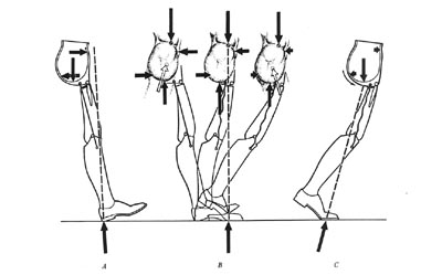 A radical departure, later termed the "Canadian" design, was introduced by McLaurin in 1954 (Fig 21B-2.). This unique approach demonstrated the feasibility of using unlocked hip, knee, and ankle joints that relied on biomechanics to achieve stance-phase stability while permitting flexion at the hip and knee during swing phase.
This is now the standard for prosthetic fitting worldwide, and locking joints are very rarely necessary. A molded plastic socket encloses the ischial tuberosity for weight bearing, extends over the crest of the ilium to provide suspension during swing phase, and affords excellent mediolateral trunk stability by fully encasing the contralateral pelvis. The prosthetic hip joint is attached to the socket anteriorly, and this results in excellent stance-phase stability plus good swing-phase flexion.
HIP JOINT MECHANISMS
The sections dealing with joint and foot mechanisms are reprinted, with minor modifications, from Michael J: Clin Prosthet Orthot 1988; 12:99-108.
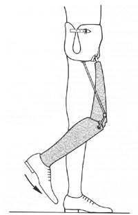
One of the inherent limitations of the Canadian design is that the prosthesis must be significantly short (1 cm+) to avoid forcing the amputee to vault for toe clearance. Fig 21B-3. and Fig 21B-4. illustrate why this is so. At toe-off, the heel rises up during knee flexion and pulls the hip joint firmly against its posterior (extension) stop. The thigh segment remains vertical until the knee has reversed its direction of motion and contacted the knee stop. Only then does the thigh segment rotate anteriorly and cause the hip joint to flex. In essence, the prosthesis is at its full length during midswing. Since the patient has no voluntary control over any of the passive mechanical joints, the prosthetist is forced to shorten the limb for ground clearance.
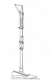
In an effort to overcome this limitation, the hip flexion bias system was developed for the young, active amputee who wished to walk rapidly. At toe-off, kinetic energy from the coil spring is released, and the prosthetic thigh is thrust forward. Not only does this provide the amputee with a more normal-appearing gait, it also improves ground clearance. As a result, the prosthesis can be lengthened to a nearly level configuration in most cases (Fig 21B-5.). However, two potential problems have been noted with this approach. One is the development of annoying squeaks in the spring mechanisms after a few months of use, which sometimes tend to recur inexorably. A more significant concern is that as the spring compresses between heel strike and midstance, it creates a strong knee flexion moment. Unless this is resisted by a stance control knee with a friction brake or a polycentric knee with inherent stability, the patient may fall. Since the friction-brake mechanisms lose their effectiveness as the surface wears, the polycentric knee is the preferred component with this hip mechanism.
Another hip joint option is the Otto Bock four-bar knee disarticulation joint mounted in reverse as proposed by Peter Tuil of The Netherlands (Fig 21B-6.). Benefits claimed are parallel to those expected from a polycentric knee unit: increased ground clearance during swing phase due to the inherent "shortening" of the linkage in flexion and enhanced stability at heel strike amputees comment favorably on the smooth deceleration and good appearance while sitting that this joint offers.
KNEE JOINT MECHANISMS
 Other than the exception discussed above, knee mechanisms are selected by the same criteria as for transfemoral (above-knee) amputees. The single-axis (constant-friction) knee remains the most widely utilized due to its light weight, low cost, and excellent durability. Friction resistance is often eliminated to ensure that the knee reaches full extension as quickly as possible. A strong knee extension bias enhances this goal and offers the patient the most stable biomechanics possible with this mechanism. Although the single-axis type was proposed as the knee of choice for the Canadian hip disarticulation design, more sophisticated mechanisms have proved their value and are gradually becoming more common.
The friction-brake stance control (safety) knee is probably the second most frequently utilized component. Because there is very little increase in cost or weight and reliability has been good, many clinicians feel that the enhanced knee stability justifies this approach, particularly for the novice amputee. Missteps causing up to 15 degrees of knee flexion will not result in knee buckle, which makes gait training less difficult for the patient and therapist. The major drawback to this knee is that the limb must be non-weight bearing for knee flexion to occur. Although this generally presents no problem during swing phase, some patients have difficulty in mastering the weight shift necessary for sitting. It should be noted that use of such knee mechanisms bilaterally must be avoided. Since it is impossible for the amputee to simultaneously unload both artificial limbs, sitting with two stance control knees becomes nearly impossible.
A third type that has proved advantageous for this level of amputation is the polycentric (four-bar) knee. Although slightly heavier than the previous two types, this component offers maximum stance-phase stability. Because the stability is inherent in the multilinkage design, it does not erode as the knee mechanism wears during use. In addition, all polycentric mechanisms tend to "shorten" during swing phase, thus adding slightly to the toe clearance at that time. Many of the endoskeletal designs feature a readily adjustable knee extension stop. This permits significant changes to the biomechanical stability of the prosthesis, even in the definitive limb. Because of the powerful stability, good durability, and realignment capabilities of the endoskeletal polycentric mechanisms, they are particularly well suited for the bilateral amputee. Patients with all levels of amputation, up to and including translumbar (hemicorporectomy), have successfully ambulated with these components.
At first glance, a manual locking knee seems a logical choice. However, experience has shown that this is rarely required and should be reserved as a prescription of last resort. Only additional medical disabilities such as blindness will require this mechanism. Unlocking the knee joint in order to sit requires the use of one hand in the unilateral case; expecting a bilateral amputee to cope with dual locking knees and dual locking hips is unrealistic. Furthermore, in the event of a fall backwards, fully locked joints may prevent the amputee from bending his trunk to protect his head from impact.
For many years, the use of fluid-controlled knee mechanisms for high-level amputees was considered unwarranted since these individuals obviously walked at only one (slow) cadence. The development of hip flexion bias mechanisms and more propulsive foot designs have challenged this assumption. Furthermore, a more sophisticated understanding of the details of prosthetic locomotion has revealed an additional advantage of fluid control for the hip-level amputee.
It is well accepted that any fluid-control mechanism (hydraulic or pneumatic) results in a smoother gait. Motion studies conducted at Northwestern University have confirmed that a more normal gait for the hip dis-articulation/transpelvic amputee is also produced. Gait analysis has demonstrated that utilization of a hydraulic knee in a hip disarticulation prosthesis results in a significantly more normal range of motion at the hip joint during the walking cycle than is possible with conventional knees. In addition, a more rapid cadence was also possible.
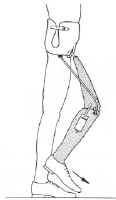 The preferred mechanism has separate knee flexion and extension resistance adjustments. A relatively powerful flexion resistance limits heel rise and initiates forward motion of the shank more quickly. In essence, the limb steps forward more rapidly. As the shank moves into extension, the fluid resistance at the knee transmits the momentum up to the thigh segment and pushes the hip joint forward into flexion. In effect, the fluid-controlled knee results in a hip flexion bias (Fig 21B-7.).
Richard Lehneis et al. have reported on a coordinated hip-knee hydraulic linkage using a modified Hy-drapneumatic unit. This adaptation provides a hip extension bias and has resulted in a smoother gait(Fig 21B-8.).
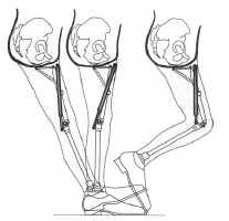 Finally, a number of new components have been developed recently that combine the characteristics of some of the above classes of knee mechanisms. For example, Teh Lin manufactures a "Graphlite" knee consisting of a polycentric unit with pneumatic swing-phase control in a carbon fiber receptacle. Such "hybrid" designs are expected to increase over the next few years.
FOOT MECHANISMS
Traditionally, the solid-ankle cushion-heel (SACH) foot has been recommended for the Canadian hip disarticulation design due to its moderate weight, low cost, and excellent durability. So long as the heel durometer is very soft, knee stability with this foot has generally been quite acceptable.
In those cases where slightly more knee stability is desired, a single-axis foot with a very soft plantar flexion bumper is preferred. Added weight, maintenance, and cost plus reduced cosmesis are the liabilities of this component.
Multiaxis feet (such as the Greissinger) have liabilities similar to the single-axis versions but add extra degrees of freedom in hindfoot inversion/eversion and transverse rotation. In addition to accommodating uneven ground, absorbing some of the torque of walking, and protecting the patient's skin from shear stresses, multiaxis feet seem to decrease the wear on the other prosthetic mechanisms as well.
In the last 5 years, more sophisticated foot mechanisms have reached the market, and all have been demonstrated to function successfully for the high-level amputee. The solid-ankle flexible-endoskeleton (SAFE) foot inaugurated a class that could be termed "flexible-keel" designs. Other members of this class include the STEN foot and the Otto Bock Dynamic foot. All are characterized by a softer, more flexible forefoot that results in a smoother rollover for the patient. The SAFE version offers some transverse rotation as well.
In general, a softer forefoot requires special care during dynamic alignment to ensure that knee buckle does not occur inadvertently. However, when used in concert with a polycentric knee, the reverse occurs: the prosthesis actually becomes more stable during late stance phase. The polycentric knee mechanism strongly resists a bending moment, which leads to its powerful stability at heel strike. It flexes during swing phase only if the forefoot remains firmly planted on the floor as the body "rides" the prosthesis over it. This creates a shearing force that disrupts the linkage and permits easy flexion of the knee. Because the softer flexible keel delays this shearing moment, the polycentric knee is actually more stable in late stance than with a more rigid foot.
Dynamic-response feet, which provide a subjective sense of active push-off, can also be used to advantage for the hip-level amputee. The Carbon Copy II, Seattle foot, Springlite, and Flex-Foot have all been successfully utilized for this type of patient. They seem to provide a more rapid cadence, as noted by one long-term hip disarticulation wearer, who stated after receiving a Seattle foot, "For the first time in my life I can pass someone in a crowd."
Once again, the interaction between the foot and knee must be carefully monitored. In general, the more responsive the foot mechanism, the more important the knee unit resistances become. Many clinicians prefer fluid-controlled knees, or at least one with powerful friction cells. Otherwise, much of the forward momentum of the shank can be wasted as abrupt terminal impact of the knee. Presumed reductions in energy consumption with the newer feet have not yet been documented by scientific studies for this level of amputation but have been demonstrated under certain circumstances for transtibial amputees.
In addition to foot mechanisms, several ankle components have recently reached the American market. These can be paired with most of the feet mentioned above to add additional degrees of motion as desired. Examples include the SwePro ankle from Sweden, The Blatchford (Endolite) Multi-Flex ankle from England, and the Seattle ankle.
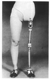 Torque-absorbing devices are often added to hip dis-articulation/transpelvic prostheses to reduce the shear forces transmitted to the patient and components. Ideally, they are located just beneath the knee mechanism (Fig 21B-9.). This increases durability by placing the torque unit away from the sagittal stresses of the ankle while avoiding the risk of introducing swing-phase whips (which can occur if it is placed proximal to the knee axis). The major justification for such a component is that the high-level amputee has lost all physiologic joints and, hence, has no way to compensate for the normal rotation of ambulation.
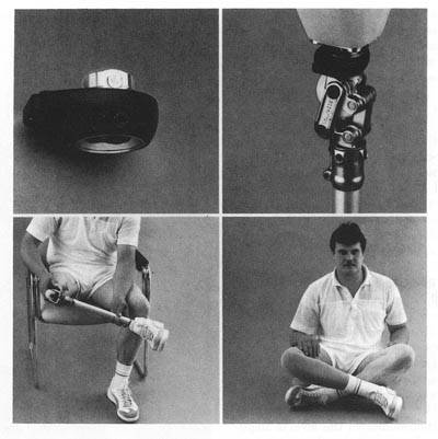 Finally, transverse-rotation units or positional rotators originally developed for the Oriental world have become available worldwide. Installed above the knee mechanism, these devices permit the amputee to press a button and passively rotate the shank 90 degrees or more for sitting comfort (Fig 21B-10.). They not only facilitate sitting cross-legged upon the floor but also permit much easier entry into restaurant booths and other confined areas. This component is particularly advantageous for entering and exiting automobiles.
SOCKET DESIGNS AND CASTING TECHNIQUES
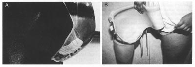 The most important part of any prosthesis is the socket, which provides the man-machine interface. During the initial assessment of the amputee, examination of postoperative radiographs and careful palpation of the pelvis are recommended. Some amputees present as "hip disarticulation" when they have a short femoral segment remaining or as "transpelvic" when part of the ilium, sacrum, or ischium remains. Unanticipated bony remnants can become a puzzling source of discomfort. On the other hand, they may sometimes be utilized to assist suspension or rotary control or to provide partial weight-bearing surfaces. Due to the success of ischial containment transfemoral sockets, the importance of precise contours at the ischium and ascending ramus is now more widely recognized. The same principles can readily be applied to hip disarticulation sockets to increase both comfort and control (Fig 21B-11.).
We prefer to have the amputee simulate weight bearing during the plaster impression technique to create as precise a mold as possible. However, in contrast to the technique advocated by Otto Bock, we believe that careful attention to shaping the medial wall in the ischial region is important to improve control of the prosthesis for both walking and sitting.
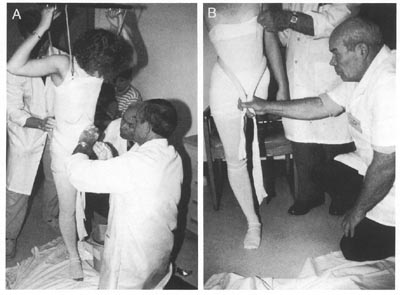 A sling suspension system should be utilized, in addition, to firm up redundant soft tissue for obese individuals or transpelvic amputees. (A casting platform alone will suffice for many hip disarticulates, especially those of slight build.) Soft rubber tubing or a similar shaping device can be pulled snugly about the waist just proximal to the iliac crests to ensure good definition of this critical suspension area and simultaneously define the contours of the thoracolumbar region (Fig 21B-12.). If the distance from the iliac crest to the ischial tuberosity is too large in the mold, the socket will piston up and down with every step.
Prior to the removal of the plaster mold, the ischial tuberosity area may be highlighted by adding more plaster splints while cupping the ischium firmly in the palm of the hand. The goal of casting is to create an exact replica of the pelvis including the often neglected areas inferior to the lateral, anterior, and posterior aspects of the iliac crest. During model rectification, relief must be provided for the inferior pubic ramus and pubic tubercle as well as the proximal edge of the iliac crests.
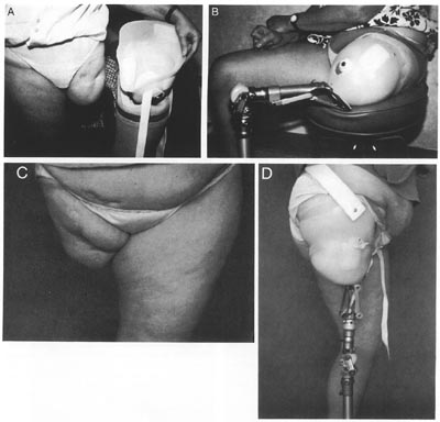
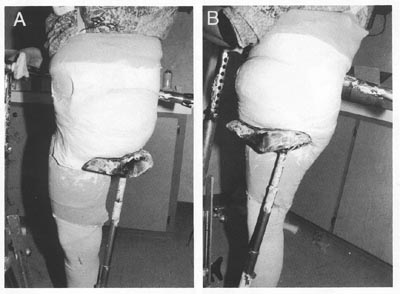 The transpelvic socket requires careful attention to the distal contours for proper weight bearing. In addition to using the sling casting technique to firm the tissues, it is useful to contour the area of the contralateral gluteal fold precisely. Although this can be done by hand, a racing-style bicycle seat makes a useful adjunct when casting (Fig 21B-13.). This contour may add a measure of gluteal bearing on the contralateral side. More importantly, it prevents the hemipelvis from slipping through the inferior border of the socket and adds significant weight-bearing stability. Good distal contours often provide sufficient weight-bearing stability to allow the proximal border of the socket to be trimmed far below the second rib margin, which was considered the proper trim line 30 years ago It is rarely necessary to extend the socket onto the thorax if the distal contours are correct.
In like manner, the anterodistal trim line should be as close to the midline as tolerable lest the panniculus protrude hernia-like during weight bearing. The male genitalia should be placed to the side prior to casting to permit the smallest practical anterodistal opening for the transpelvic socket. Although firm oblique counter-pressure toward the midline does reduce perineal shearing forces, as noted by Lyquist, it should not be overdone. Gentle contouring with the palm of the hand, combined with the sling suspension provides sufficient compression.
Many materials are suitable for socket fabrication. As is the case with other levels of lower-limb amputation, the most commonly utilized socket material is a rigid thermosetting resin: polyester or acrylic. An increasing trend toward more flexible thermoplastic materials is evident, as in other aspects of prosthetic practice. One of the authors (J.W.M.) has fitted more than two dozen polypropylene/polyethylene copolymer sockets for hip-level amputation over the past decade with good long-term results in durability, comfort, and patient acceptance (Fig 21B-14.).
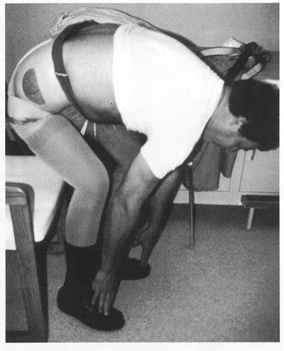 The recent advent of laminating silicone rubbers allows even more flexibility than do available thermoplastics. As was noted earlier, the resulting comfort and range of motion has been associated with significantly higher rates of prosthetic usage. Although the fabrication is complex and difficult and the finished result slightly heavier than thermoplastic designs, favorable patient response and good durability recommend further development and more widespread application of this technique. The senior author (T.v.d.W.) has fitted 35 silicone rubber sockets over the past 2 years. Amputees who have previously worn more rigid designs typically describe the rubberized sockets as feeling "more natural" or "more like a part of me" (Fig 21B-15.).
Suction Suspension
 Nearly 40 years ago, Hutter reported a single case of successful fitting of a transfemoral suction socket to a hip disarticulate with a mass of redundant tissue distal to the ischium. The senior author (T.v.d.W.) has personally fitted three such cases recently (Fig 21B-16.). Each was able to ambulate successfully and to retain full suction suspension with only the assistance of a thin, elastic Silesian belt despite the total absence of any femur. The major difference in socket configuration is the creation of a trough like channel to contain both the medial and lateral aspects of the ischiopubic ramus since no femur remains. Such fittings have been done on an experimental basis where there is sufficient residual muscle tissue to create both suction suspension and biomechanical "locking" to stabilize the socket on the patient. This approach warrants further follow-up and evaluation to determine its practicality.
CONCLUSIONS
Although wearing a transpelvic or hip disarticulation prosthesis may be cumbersome, when fitted within a few weeks of amputation, the initial acceptance rate appears to be similar to that for transfemoral amputation. Immediate postoperative fitting is technically feasible but rarely performed today. Long-term wearing rates increase significantly when sockets are comfortable, flexible, and carefully aligned. In view of the magnitude of loss at this level, application of newer, sophisticated joint and foot mechanisms is often helpful. Every case requires review on its own merits; careful attention to socket design, components, and alignment ultimately determines the effectiveness of the prosthesis.
References:
Banzinger E: Hip disarticulation prosthesis for infants (abstract). J Assoc Child Prosthet Orthot Clin 1988;
23:37.
Brittain HA: Hindquarter amputation. J Bone Joint Surg 1949; 31:404-409.
Campbell J, Childs C: The S.A.F.E. foot. Orthot Prosthet 1980; 34: 3-17.
Coley BL, Higinbotham NL, Romieu C: Hemipelvec-tomy for tumors of bone: Report of fourteen cases. Am J Surg 1951; 82:27-43.
Dankmeyer CH Jr: Prosthetic management of adult hemicorporectomy and bilateral hip disarticulation amputees. Orthot Prosthet 1981; 35:11-18.
Davis BP, Warner R, Daniel R, et al: The problem of fitting a satisfactory prosthesis following hemipelvectomy. Inter-Clin Info Bull 1964; 3:5-9.
Desio MA, Leonard JA: Above-knee prosthesis for hip disarticulation (abstract). Arch Phys Med Rehabil 1986; 67:667-668.
Foort J: Construction and fitting of the Canadian-type hip-disarticulation prosthesis. Artif Limbs 1957; 4:39-51.
Foort J: Some experience with the Canadian-type hip-disarticulation prosthesis. Artif Limbs 1957; 4:52-70.
Foort J, Radcliffe CW: The Canadian-Type Hip-Disartic-ulation Prosthesis. Project Berkeley, University of California, Prosthetic Devices Research Project, 1956.
Friedmann LW: Comments and observations regarding hemipelvectomy and hemipelvectomy prosthetics. Orthot Prosthet 1967; 21:271-273.
Giaccone V, Stack D: Temporary prosthesis for the hip-disarticulation amputee. Phys Ther 1977; 57:1394-1396.
Gillis L: A new prosthesis for disarticulation at the hip. J Bone Joint Surg 1968; 50:389-391.
Glattly HW: A preliminary report on the amputee census. Artif Limbs 1963; 7:5-10.
Greene M: Four bar knee linkage analysis. Orthot Prosthet 1983; 37:15-24.
Hampton F: A hemipelvectomy prosthesis. Artif Limbs 1964; 8:3-27.
Hampton F: A Hemipelvectomy Prosthesis. Chicago, Northwestern University Prosthetic Research Center, 1964, p 32.
Haslam T, Wilson M: Hip Flexion Bias, Concept 80. Houston, Medical Center Prosthetics, 1980.
Huang CT: Energy cost of ambulation with Canadian hip disarticulation prosthesis. J Med Assoc State Ala 1983; 52:47-48.
Hutter CG: Improved type of hip-disarticulation on prosthesis. J Bone Joint Surg [Am] 1953; 35:745-748.
Hutter CG: Suction-socket prosthesis for a hip-disarticulation amputee. J Bone Joint Surg [Am] 1953; 35:230-232.
Imler C, Quigley M: A technique for thermoforming hip disarticulation prosthetic sockets. J Prosthet Orthot 1990; 3:34-37.
Iwakura H, Abe M, Fujinaga H, et al: Locomotion of the hemipelvectomy amputee. Prosthet Orthot Int 1979; 3:111-114.
Jay GR, Sabolich L: A bilateral above-knee/hip disarticulation fitting. Inter-Clin Info Bull 1972; 11:9-12.
Jensen JS, Mandrup-Poulsen T: Success rate of prosthetic fitting after major amputations of the lower limb. Prosthet Orthot Int 1983; 7:119-122.
Johansson H, Olerud S: Traumatic hemipelvectomy in a ten-year-old boy. J Bone Joint Surg [Am] 1971; 53:170-172.
Klasen HJ, Ten Duis HJ: Traumatic hemipelvectomy. J Bone Joint Surg [Br] 1989; 71:291-295.
Koskinen EVS: Hemipelvectomy for malignant tumours of bone: A study with preoperative arteriographic examination of the growth. Ann Chir Gynaecol 1967; 56:9-17.
Krajbich I, De Bari A, Hubbard S, et al: Surgical and prosthetic-orthotic treatment of patients with unilateral congenital or early childhood hip disarticulation or hemipelvectomy (abstract). J Assoc Child Prosthet Orthot Clin 1988; 23:37.
Lee CM, Alt LP: Hemipelvectomy and hip disarticulation for malignant tumors of the pelvis and lower extremity. Ann Surg 1953; 137:704-717.
Lehneis HR, et al: Prosthesis management of the cancer patient with high level amputation. Orthot Prosthet 1981; 35:10-28.
Lehneis HR, et al: Prosthetics Management for High Level Lower Limb Amputees. New York, Institute of Rehabilitation Medicine, 1980.
Leppanen RE: A temporary prosthesis for hip disarticulation. Phys Ther 1969; 49:987-990.
Levesque CM, Gauthier-Gagnon C, Beauregard M: An endoskeletal hip disarticulation prosthesis for the toddler. J Prosthet Orthot 1991; 3:120-124.
Littig DH, Lundt JE: The UCLA anatomical hip disarticulation prosthesis. Clin Prosthet Orthot 1988; 12:114-118.
Lyquist E: Canadian-type socket for a hemipelvectomy. Artif Limbs 1958; 5:130-132.
Lyquist E: New hip joint for Canadian-type hip-disarticulation prosthesis (technical note). Artif Limbs 1958; 5:129-130.
Madden M: The flexible socket system as applied to the hip disarticulation amputee. Orthot Prosthet 1985; 39:44-47.
Marx HW: Some experience in hemipelvectomy prosthetics. Orthot Prosthet 1967; 00:259-270.
McLaurin CA: Hip Disarticulation Prosthesis, Report No. 15. Toronto, Canada, Prosthetic Services Centre, Department of Veterans Affairs, 1954.
McLaurin CA: The evolution of the Canadian-type hip disarticulation prosthesis. Artif Limbs 1957; 4:22-28.
McLaurin CA, Hampton F: Diagonal Type Socket for Hip Disarticulation Amputees. Chicago, Northwestern University Prosthetic Research Center, Publication V.A.-V1005 M 1079, 1961.
Meester GL, Myerley WH: Traumatic hemipelvectomy: Case report and literature review. J Trauma 1975; 16:541-545.
Michael J: Component selection criteria: Lower limb disarticulations. Clin Prosthet Orthot 1988; 12:99-108.
Michael J: Energy storing feet: A clinical comparison. Clin Prosthet Orthot 1987; 11:154-168.
Michael J: Overview of prosthetic feet. Instr Course Lect 1990; 39:367-372.
Murphy EF: Danish experience with Canadian HD (technical note). Artif Limbs 1958; 5:132-133.
Nader M, et al: Polycentric, Four Bar Linkage Knee Joint, Technical Information Bulletin No. 45. Duders-tadt, West Germany, Otto Bock Industries, 1986, p 3.
Nilsonne U, Hjelmstedt A, Hakelus A. Surgical problems in hemipelvectomy. Acta Orthop Scand 1968; 39:161-170.
Ockenfels PA: Management and construction procedure of bilateral split-bucket type hip disarticulation prosthesis. Orthot Prosthet 1968; 22:29-36.
Oppenheim WL, Tricker J, Smith RB: Traumatic hemipelvectomy-The tenth survivor: A case report and a review of the literature. Injury 1978; 9:307-312.
O'Riain M: Clinical Data on Floor Reaction Forces- Shear (report). Royal Ottawa Rehabilitation Center, 1985.
Pack GT, Ehrlick H: Hip joint exarticulation and sacroiliac disarticulation. Ann Surg 1946; 123:965-985.
Pinzur MS, et al: An easy-to-fabricate modified hip disarticulation temporary prosthesis (technical note). Orthot Prosthet 1986; 40:58-60.
Radcliffe CW: The biomechanics of the Canadian-type hip-disarticulation prosthesis. Artif Limbs 1957; 4:29-38.
Sabolich J: Contoured adducted trochanteric-controlled alignment method (CAT-CAM): Introduction and basic principles. Clin Prosthet Orthot 1985; 9:15-26.
Sabolich J, Guth T: The CAT-CAM-HD. A new design for hip disarticulation patients. Clin Prosthet Orthot 1988; 12:119-122.
Seaton DG, Wilson LA, Shepherd WG: Clinical trial of the diagonal socket prosthesis for hip disarticulation amputation. Inter-Clin Info Bull 1972; 11:1-8, 17.
Shurr DG, Cook TM, Buckwalter JA, et al: Hip disarticulation: A prosthetic follow-up. Orthot Prosthet 1983; 37:50-57.
Simons BC, Lehman JF, Taylor H, et al: Prosthetic management of hemicorporectomy. Orthot Prosthet 1968; 22:63-68.
Solomonidis SE, Loughran AJ, Taylor J, et al: Biomechanics of the hip disarticulation prosthesis. Prosthet Orthot 1nt 1977; 1:13-18.
Svetz WR, Wagner C, Clark MW: A young hemipelvectomy patient. Inter-Clin Info Bull 1976; 15:9-13.
Tuil P: The hip disarticulation prosthesis as developed by the O.I.M. Noord Nederland. Clin Prosthet Orthot 1988; 12:109-113.
Van der Waarde T: Ottawa experience with hip disarticulation prostheses. Orthot Prosthet 1984; 38:29-33.
Van Vorhis RL, Childress DS: Kinematic aspects of the Canadian hip disarticulation prosthesis: Preliminary results in Murdock G (ed): Amputation Surgery and Lower Limb Prosthetics. Oxford, England, Blackwell Scientific Publications, 1988.
Vitali M, Harris EE, Redhead RG: Amputees and their prostheses in action. Ann R Coll Surg Engl 1967; 40:260-266.
Wade FV, Machsood WA: Traumatic hemipelvectomy: A report of two cases with rectal involvement. J Trauma 1965; 5:554-562.
Waters RL, et al: Energy costs of walking of amputees: The influence of level of amputation. J Bone Joint Surg [Am] 1976; 58:46.
Werne S: Two cases of hindquarter amputation. Acta Or-thop Scand 1954; 23:90-99.
Wise RA: A successful prosthesis for sacro-illiac disarticulation (hemipelvectomy). J Bone Joint Surg [Am] 1949; 31:426-430.
Zettl JH: Immediate postsurgical prosthetic fitting: The role of the prosthetist. Phys Ther 1971; 51:144-151.
Zettl JH, Van Zandt ML, Gardner J: The hip-disarticulation and short above-knee immediate postsurgical adjustable pylon prosthesis. Bull Prosthet Res 1970; 10:64-69.
Zettl JH, Van Zandt ML, Gardner J: The immediate postsurgical adjustable pylon prosthesis for the hip-disarticulation and short-above-knee amputee. Inter-Clin Info Bull 1971; 10:7-10, 16.
